A slab can look smooth and still create a material-handling problem. Small elevation changes can cause rack-mounted loads to sway, accelerate equipment wear, disrupt wire-guided vehicles, and limit a very narrow aisle truck's ability to operate at its designed lift height. Knowing how to evaluate concrete flatness means measuring the floor against the actual demands of the operation, not judging it by appearance or a quick pass with a straightedge.
For industrial facilities, flatness is a performance requirement. The right evaluation method depends on whether the floor supports general forklift traffic, high-bay racking, VNA equipment, wire guidance, or a floor upgrade project where existing defects must be quantified before repair.
Start With the Floor's Operational Requirement
Concrete flatness is not a single universal standard. A distribution floor carrying sit-down forklifts has a different tolerance than a VNA warehouse where turret trucks operate in fixed aisles beside high racking. The first question is not, “Is this floor flat?” It is, “Flat enough for what equipment, load, travel path, and operating speed?”
Define the operational conditions before testing. Document the truck type, wheel configuration, mast height, maximum lift height, aisle width, rack layout, travel direction, load characteristics, and whether equipment is wire-guided or rail-guided. Also identify whether the project concerns a new slab, an occupied building, a repaired area, or a facility conversion.
This distinction matters because a floor can meet a general flatness specification while remaining unsuitable for high-lift, defined-traffic operations. In VNA environments, deviations in the wheel paths have a direct effect on truck stability and mast movement. Broad random-traffic results do not automatically prove defined-traffic performance.
Understand Flatness, Levelness, and Floor Profile
Flatness describes short-wavelength surface variation. It reflects the local bumps and dips that affect wheel movement over relatively short distances. Levelness describes longer-wavelength elevation change across a floor. Both matter, but they affect operations differently.
For many conventional slabs, flatness and levelness are expressed as FF and FL values. Higher numbers indicate a flatter or more level floor. These values are commonly established through profile measurements and statistical analysis under ASTM E1155. They are useful for random-traffic floors, where vehicles can travel in many directions across the slab.
Defined-traffic floors require a more targeted approach. A VNA truck repeatedly travels the same wheel tracks, so the critical measurement is the profile along those tracks, not the average condition of the entire slab. F-min testing is commonly used for this purpose. It evaluates the floor's longitudinal and transverse profile in the specific paths where the truck's wheels operate.
A useful way to view the difference is this: FF/FL evaluates the general character of a floor, while F-min evaluates whether a defined aisle can support a specific high-performance operation. The correct method depends on the use case and the governing project specification.
Do Not Treat a Straightedge Check as Final Acceptance
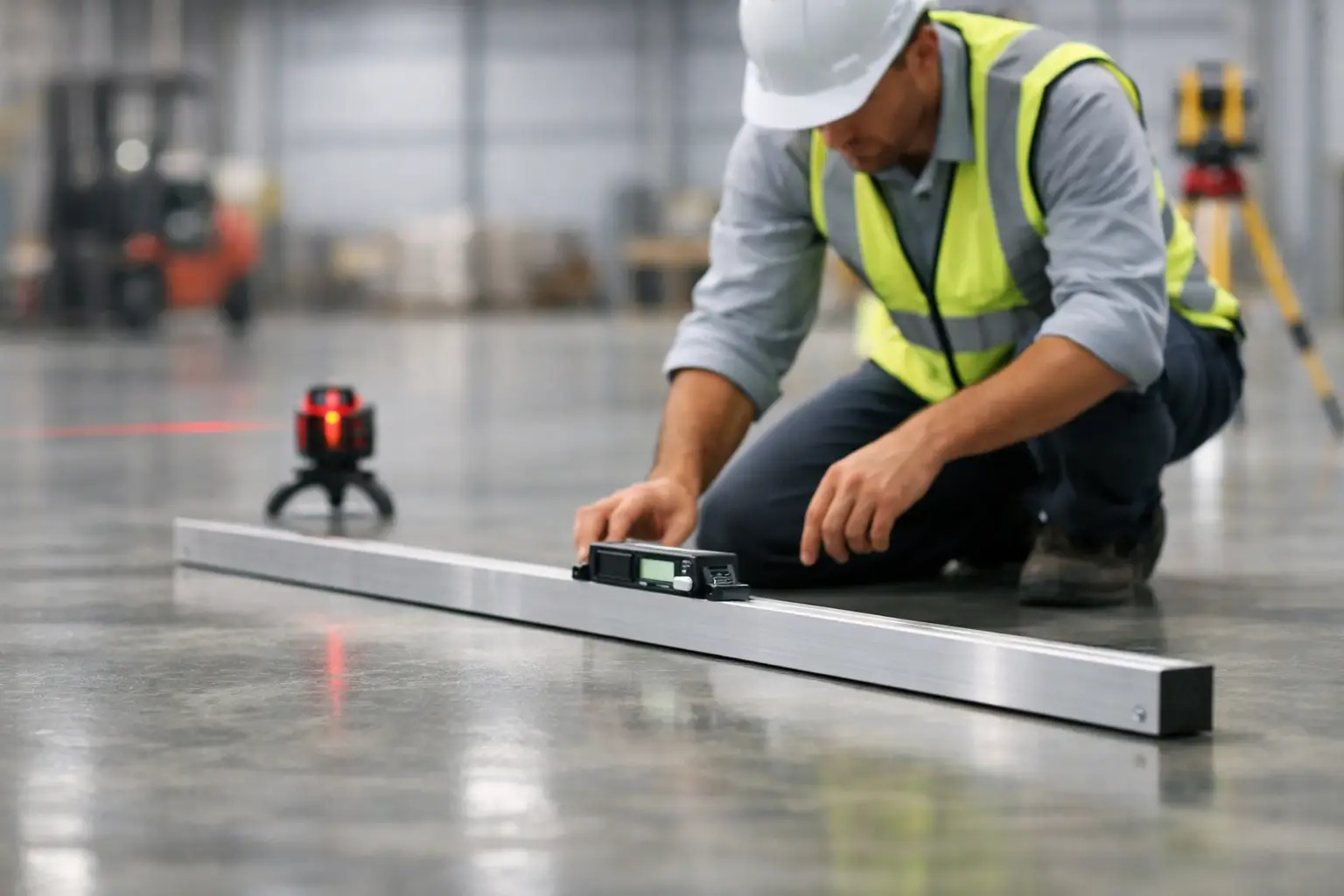
A 10-foot straightedge can identify obvious ridges, curled joints, and localized depressions. It is practical during construction quality checks and valuable when locating repair areas. It is not a complete substitute for formal profile testing on a floor with demanding industrial requirements.
A straightedge provides isolated readings. It does not establish the continuous wheel-path data needed to assess VNA suitability, nor does it provide the statistical detail associated with ASTM E1155 testing. Use it as a diagnostic tool, not as the sole basis for accepting or rejecting a critical floor.
Select the Right Measurement Method
The testing approach should match the operational risk. For general warehouse, manufacturing, and commercial industrial spaces, a floor-profile survey may establish FF/FL values across a representative grid. Measurements should be taken with calibrated equipment and processed according to the applicable standard and project requirements.
For superflat or VNA floors, measurement should follow the actual or planned truck wheel paths. The survey needs to account for the truck's wheelbase, gauge, and guidance arrangement. A floor profile that appears acceptable at the center of an aisle may still have unacceptable deviations at the left and right wheel tracks.
Modern electronic floor profilers collect frequent elevation data and generate repeatable reports. Laser-based survey tools can also help establish elevations, identify broad settlement, and map repair scopes. The value is not the instrument alone. It is the testing plan, calibration, data interpretation, and comparison to the specified acceptance criteria.
When evaluating an existing facility, test enough of the operating area to reveal patterns rather than isolated defects. Include representative aisles, high-traffic intersections, loading approaches, rack aisles, door thresholds, and areas near joints or previous repairs. If a problem is reported in a particular location, collect extended readings before and after that point to determine whether the condition is local or systemic.
Test at the Right Time
Timing affects concrete floor measurements. A new slab can change as moisture leaves the concrete and the slab curls near joints, walls, columns, and changes in restraint. Early testing confirms construction quality and allows timely correction. Later testing may be necessary when final operating conditions, racking, and traffic patterns are established.
The project specification should state when measurements will occur, the testing method, the sampling plan, and the acceptance thresholds. Without those details, disputes can arise over whether a later change in floor profile is a placement issue, normal slab movement, heavy-use damage, or a condition caused by environmental exposure.
For existing floors, evaluate conditions under normal operating temperatures and loading whenever possible. A floor that is dry and unloaded during a weekend survey may behave differently during active production, washdown cycles, or seasonal temperature changes. The goal is to understand the floor as the operation experiences it.
Review the Data Against Use, Not Just a Number
A flatness report should identify where the floor is out of tolerance, how severe the variance is, and whether it affects the intended equipment. Avoid relying on a single overall average. A strong average can mask a limited number of critical defects in an aisle, at a joint, or near a rack leg.
Review results in relation to the floor plan. Mark problem areas against rack lines, traffic directions, joints, drainage points, and transitions to adjacent slabs. In VNA applications, compare the data to the truck manufacturer's requirements and the specified defined-traffic criteria. The truck supplier, rack engineer, floor contractor, and facility team should be aligned before equipment is commissioned.
Where floor flatness is deficient, determine the cause before selecting a remedy. Common causes include curled joints, uneven placement, slab settlement, abrasion and wear, failed joint fillers, localized spalling, previous patching, or incompatible repairs. Grinding may correct high spots and improve profile continuity, but it cannot solve every condition. Low areas, settlement, structural movement, or extensive deterioration may require more substantial repair or a different floor upgrade strategy.
Evaluate Joints and Transitions Separately
Joints are often the first locations where flatness-related operating issues become visible. Heavy forklift crossings can break joint edges, dislodge fillers, and create impact points that worsen over time. Even when the slab profile is acceptable between joints, a failed joint can affect ride quality, loads, wheels, and equipment maintenance.
Inspect joint condition alongside profile data. Look for edge damage, differential elevation, open joints, filler failure, and signs of repeated impact. Transitions at dock doors, slab additions, pits, drains, and equipment pads also deserve focused measurement. These are high-risk locations for abrupt changes in elevation.
For wire-guided VNA systems, verify the relationship between wire location, wheel paths, and floor profile. Guidance accuracy does not compensate for an unsuitable slab. The floor and guidance system must work together to maintain stable, predictable truck travel.
Build an Evaluation Plan Before Construction or Upgrade
The lowest-risk approach is to establish performance criteria before a slab is placed or a facility conversion begins. The plan should identify the floor classification, testing standard, equipment, test timing, sampling density, acceptance criteria, and responsibility for review. It should also define what happens if results fall outside the requirement.
For active facilities, sequence testing and corrective work around operations. A targeted grinding or joint repair program can often be completed in phases, limiting disruption to critical traffic areas. The scope should be based on measured conditions, not assumptions. Over-grinding can reduce cover, expose aggregate, or create unwanted transitions; under-correcting leaves the operational risk in place.
Osis Group approaches floor evaluation as part of long-term facility performance. Accurate measurement, disciplined interpretation, and repair methods matched to the defect give operations teams a defensible path from reported ride issues to a floor condition that supports safe, productive use.
The most useful flatness evaluation does more than produce a report. It gives the facility team a clear decision: accept the floor, monitor it, repair targeted areas, or upgrade the surface before it becomes a constraint on equipment, safety, or uptime.