
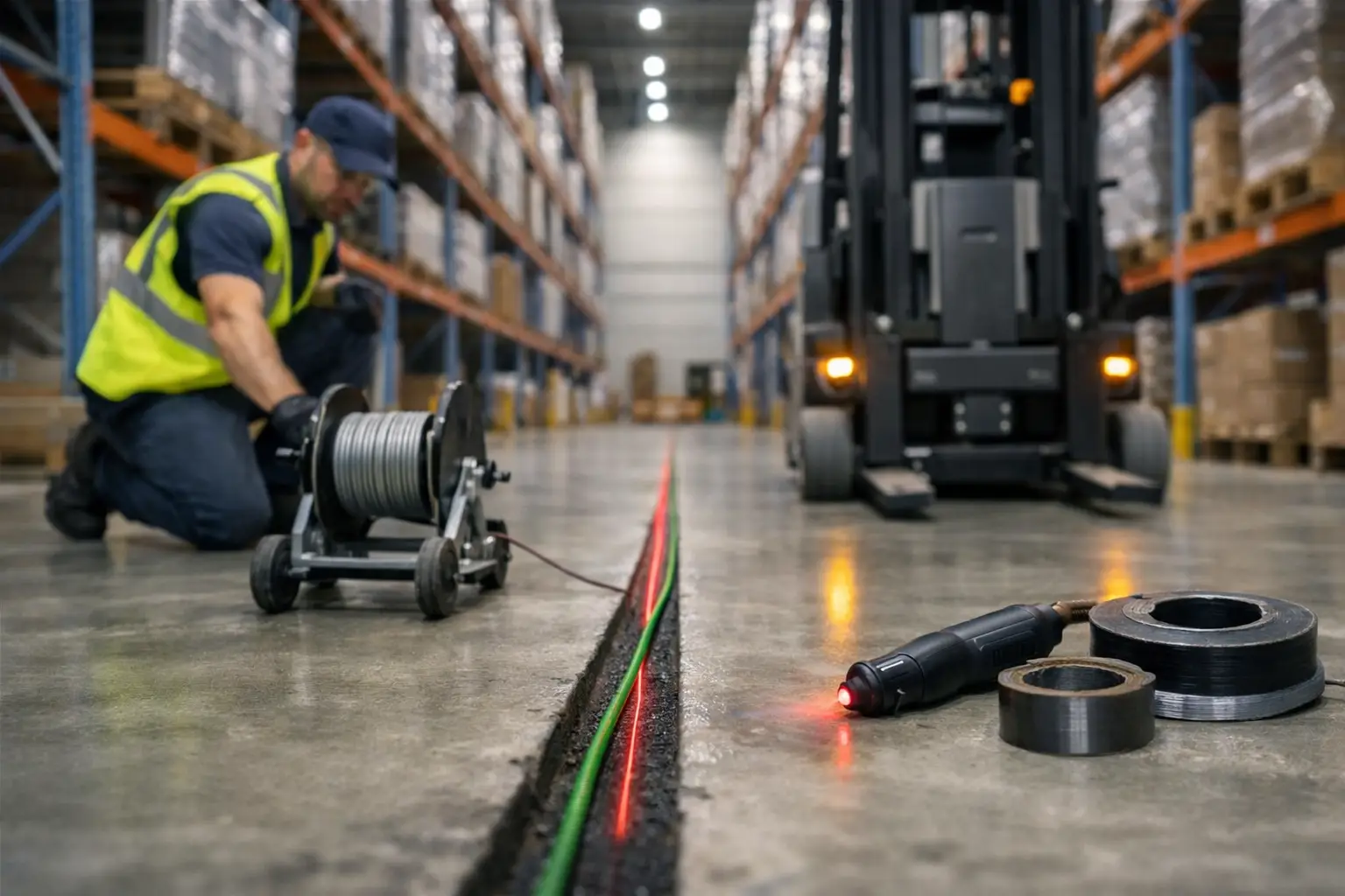
A wire-guided very narrow aisle truck can only perform as accurately as the guidance path beneath it. A poorly located wire, inconsistent saw cut, weak channel repair, or incomplete commissioning can create truck tracking faults, rack-strike risk, and avoidable downtime. Knowing how to install wire guidance systems starts with treating the work as a precision floor-installation process, not simply an electrical task.
Wire guidance is often installed in facilities where aisle width, lift height, rack clearances, and productivity leave little room for error. The installation must align with truck manufacturer requirements, rack geometry, floor flatness conditions, and the operating plan for the facility. Quality control at every stage protects the investment in the VNA operation.
Start With the Operating Requirements
The correct wire guidance design depends on the truck fleet and the warehouse layout. Before marking a single aisle, confirm the equipment manufacturer’s requirements for wire type, installation depth, loop configuration, transmitter compatibility, signal strength, and test procedures. Guidance systems are not interchangeable by assumption. A method that works for one truck model may not meet the requirements of another.
Review the approved rack layout, aisle centerlines, truck travel direction, transfer areas, and transitions. The wire must be positioned precisely relative to the intended truck path, not merely centered between rack uprights. In a VNA aisle, a small offset can affect the truck’s travel position over the full aisle length.
The floor itself also requires evaluation. Existing slab joints, cracks, patched areas, elevated moisture exposure, and previous embedded services can affect routing and repair decisions. If the facility is active, the installation plan should define work zones, traffic separation, curing time, and the sequence for returning aisles to service. The goal is to complete the work without creating an uncontrolled interruption to warehouse operations.
Survey the Floor Before Cutting
A detailed site survey establishes the control points for the installation. Verify rack alignment, aisle dimensions, and actual floor conditions against the project drawings. Do not rely solely on design dimensions where racks have already been installed or where the slab has been repaired, upgraded, or ground after the original layout was issued.
The installation team should establish a reliable baseline and use appropriate measurement equipment to mark the wire route. Marks must be clear enough to control the saw cut but protected from traffic, dust, and cleaning activity. Recheck measurements at regular intervals and at both ends of every aisle.
Before saw cutting, scan the slab where conditions indicate potential embedded utilities, reinforcement concerns, or unknown prior work. The depth of the proposed channel must be coordinated with the slab design and project requirements. Cutting too deep can create unnecessary risk to the slab. Cutting too shallow can leave insufficient cover above the wire and make the repair more vulnerable to traffic, abrasion, or early failure.
Joint locations demand particular attention. A wire crossing a moving joint needs a detail that maintains electrical continuity while allowing the joint to function. Rigidly bridging a working joint without the correct provision can lead to a damaged wire or failed repair material. This is one area where the system design, floor condition, and manufacturer direction must be resolved before installation begins.
How to Install Wire Guidance Systems in the Slab
Once the layout is verified, saw cut the channel to the specified width and depth. The cut must be consistent. Variable depth or width makes wire placement and channel filling less controlled, which can affect both signal performance and the durability of the finished floor.
Remove all cuttings, dust, slurry, and loose concrete from the channel. This step directly affects bond performance. Industrial repair materials cannot achieve their intended bond strength when installed over contaminated or poorly prepared concrete. Vacuum cleaning is typically necessary, followed by inspection of the channel walls and base.
Place the specified guide wire continuously and without damage to its insulation. Avoid sharp bends, pinched sections, and unapproved splices. Where splices or connection points are required by the system design, they must be completed according to the equipment manufacturer’s instructions and protected within the installation detail.
Wire placement should hold the conductor at the required depth and position before the channel is filled. A wire that floats toward the surface, shifts laterally, or drops unevenly in the channel can produce inconsistent results. It can also reduce the protective cover needed to withstand forklift traffic and floor maintenance.
Before applying repair material, test the wire circuit for continuity and confirm that readings meet the system requirements. Finding a damaged conductor after the channel has been filled means reopening the floor, extending the schedule, and creating unnecessary disruption. Test results should be recorded by aisle or circuit so the completed installation has a clear quality-control record.
Select the Right Channel Repair Material
The channel repair must do more than cover the wire. It becomes part of the operating floor and must resist the traffic, impact, and abrasion expected in that aisle. The right material depends on the floor system, substrate condition, channel dimensions, temperature, and the return-to-service window.
Fast-setting materials can be valuable when an operation has limited downtime, but speed is not the only requirement. The repair must bond securely to the channel, cure consistently, and finish flush with the surrounding slab. Material selection should also account for hard-wheel forklift traffic, repetitive wheel paths, washdown exposure, and any chemical contact specific to the facility.
Fill the channel fully, consolidate the material as required, and finish it level with the adjacent floor. High spots can affect vehicle travel and wear prematurely. Low spots can trap debris, create a maintenance concern, and expose the repair edges to impact. In high-precision VNA environments, finished floor quality and guidance system quality are closely connected.
Allow the repair to cure according to its specified return-to-service requirements. Opening the aisle too early can damage the repair before it reaches the strength needed for industrial traffic. Project schedules should allow for this curing period rather than treating it as an unexpected delay.
Commission the System Before Releasing the Aisle
Electrical continuity alone does not prove that the system is ready for production. After the channel repair has cured, connect the wire guidance system to the specified transmitter and verify signal output. Then test the actual truck under operating conditions.
Run the truck through each guided aisle, including entry, exit, and transfer points. Confirm that it detects the wire correctly, tracks consistently, and disengages or transitions as intended. The truck manufacturer or qualified equipment representative should complete any required calibration and acceptance testing.
Document the final installation. A useful closeout package includes aisle identification, wire routing information, test readings, repair material details, commissioning records, and photos of key connection or transition points before they were covered. This information reduces troubleshooting time if future modifications, floor repairs, or rack changes are required.
Common Installation Failures to Avoid
Most wire guidance problems originate in planning, layout, preparation, or verification. Cutting channels from unverified lines can place the system outside truck tolerances. Inadequate cleaning can weaken the repair. Skipping pre-fill testing can conceal wire damage until the floor must be reopened.
Another frequent mistake is treating the channel repair as cosmetic work. A cracked, debonded, or uneven repair can become a traffic and maintenance issue even if the wire remains electrically functional. Similarly, ignoring slab joints and existing floor movement can create a failure point that appears months after commissioning.
For active facilities, poor work-zone control is also costly. Dust from cutting, open channels, wet repair material, and temporary electrical connections must be managed so nearby personnel and equipment remain protected. A disciplined phasing plan is usually more valuable than attempting to complete too much of the facility at once.
Wire guidance installation is a precision trade that sits at the intersection of material handling, concrete repair, and industrial floor performance. When layout, channel preparation, wire placement, repair, and commissioning are controlled as one process, the result is a guidance path built to support reliable VNA operation for the long term.