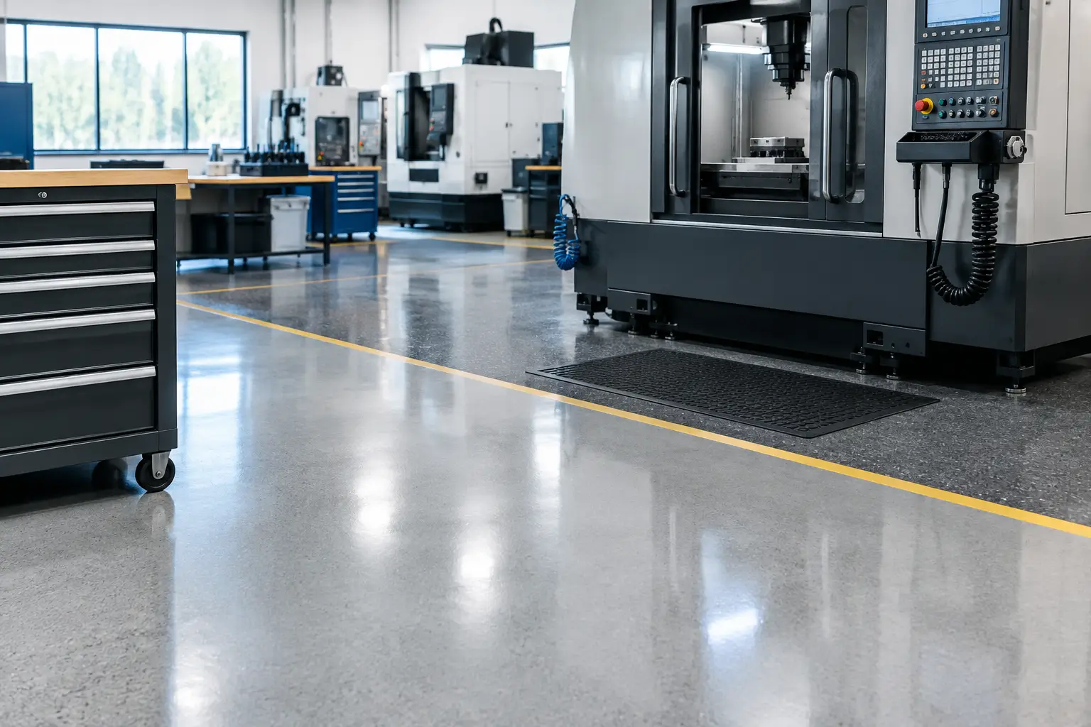
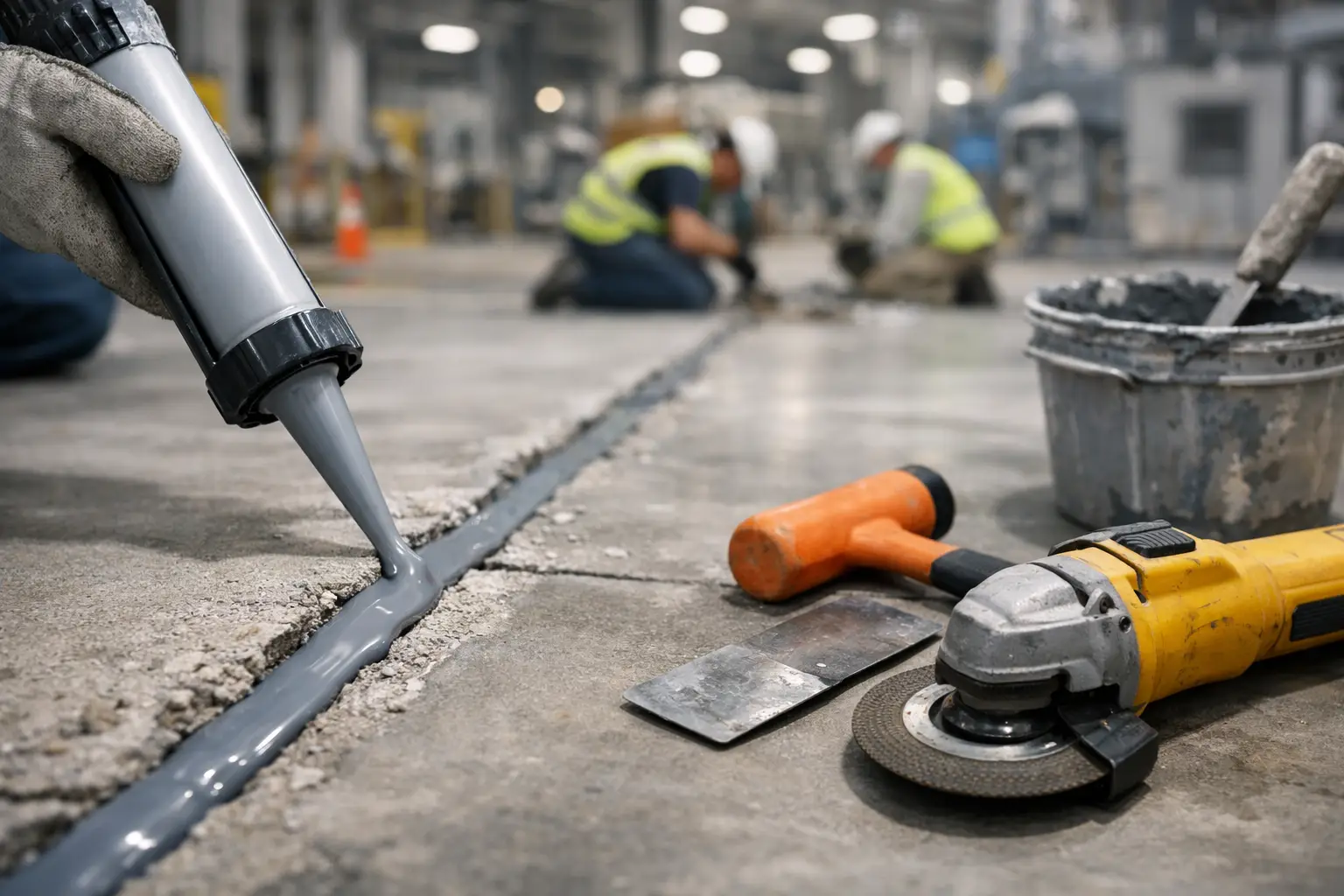
Forklift impact at a failed slab joint is rarely limited to one broken edge. Spalled concrete creates a wheel-impact point, transfers shock into the vehicle and load, accelerates further deterioration, and can disrupt safe, predictable traffic. This industrial joint repair specification guide outlines how to specify repairs that address the cause of failure, not simply fill the visible damage.
For distribution centers, plants, cold storage facilities, and other high-traffic operations, joint repairs are a floor-performance decision. The specification must account for slab movement, wheel loads, traffic direction, operating temperatures, downtime limits, and the condition of the concrete beneath the failure.
Start With the Failure Mechanism
A joint is designed to allow concrete movement while maintaining a controlled plane of separation. Repair becomes necessary when the joint edge loses support, the arris breaks down, filler debonds, or an inappropriate previous repair fractures under traffic.
The specification should begin with a field assessment. Document the joint type, joint width, spall depth and length, exposed aggregate, adjacent cracking, joint elevation, and the presence of moisture, oils, or chemical contamination. Determine whether damage is isolated or recurring along a traffic route. Repeated damage often indicates a broader issue: hard-wheel traffic crossing the joint at speed, poor load transfer, differential slab movement, inadequate joint filler, or a prior repair material that was too rigid or too weak for the service condition.
Do not treat all open joints as defects. Some joints require a compressible sealant to accommodate movement and prevent liquid intrusion. Others, especially saw-cut control joints in hard-wheel facilities, require a semi-rigid joint filler that supports the edge under traffic while allowing normal slab movement. The intended joint function determines the repair detail.
Define the Operating Conditions Before Selecting Materials
Material selection should follow service conditions, not product availability. A repair that performs in a light-duty warehouse may fail rapidly under loaded reach trucks, narrow-aisle equipment, steel wheels, or repeated pallet-jack impact.
Specify the expected traffic clearly. Include vehicle types, wheel material, maximum axle loads where available, travel patterns, turning locations, speed, and whether traffic crosses joints at a consistent angle. VNA and wire-guided forklift routes deserve close attention because repetitive wheel paths concentrate loads in narrow bands. In these areas, even a small edge failure can affect ride quality, guidance performance, and equipment reliability.
Environmental exposure also matters. Washdown areas, food and beverage operations, chemical processing spaces, freezer thresholds, and exterior loading zones may require repair systems with specific thermal, moisture, or chemical resistance. A fast-curing material may support an aggressive return-to-service schedule, but cure speed alone is not a performance standard. Confirm that the selected product can bond to the prepared substrate and sustain the actual traffic and exposure.
The specification should identify whether the repair material must be semi-rigid, flexible, cementitious, epoxy-based, polyurethane-based, or another compatible system. It should also establish required properties appropriate to the application, such as compressive strength, tensile or flexural performance, elongation, chemical resistance, and service temperature range. Product data should support the specified use, but field preparation and installation quality remain decisive.
Industrial Joint Repair Specification Guide: Scope the Repair Correctly
A reliable repair begins by removing unsound concrete. Specifications that call only for cleaning and filling a damaged joint leave too much open to interpretation. The scope should require saw-cutting or otherwise creating sound, vertical repair boundaries beyond the visible spall. Feather edges should not be accepted. They create thin material sections that are vulnerable to early fracture and debonding.
Set repair limits based on the condition of the concrete, not a fixed cosmetic width. The contractor should remove deteriorated material until competent substrate is reached, including weak concrete hidden below the surface. Where joint edges are extensively damaged, full-depth reconstruction or a wider edge-repair geometry may be required.
The repair detail also needs to preserve the joint. Bridging a moving joint with a rigid patch can transfer stress into the repair and cause a new crack beside it. Where movement is expected, the joint line must be re-established through the repair material after placement and curing. The specified joint width and filler profile should match the floor's operational requirements.
For heavily trafficked joints, consider whether load-transfer performance must be evaluated. Significant elevation difference across a joint, often called faulting, can indicate slab support or load-transfer issues that a surface repair alone will not solve. A durable specification identifies when the repair contractor must stop and report conditions that exceed the intended scope.
Require Surface Preparation That Matches the System
Surface preparation is where many joint repairs succeed or fail. Concrete must be clean, sound, and prepared to the profile required by the repair material manufacturer. The specification should call for mechanical preparation, with shot blasting, grinding, scarifying, or other methods selected to suit the repair geometry and substrate condition.
Dust, laitance, oils, old coatings, weak patch material, and curing compounds can compromise adhesion. Cleaning with a broom or compressed air is not a substitute for preparation. Vacuum collection should be required so debris does not remain in the repair cavity or migrate into active operations.
Moisture conditions need the same level of attention. Some materials tolerate damp concrete; others require a dry substrate or a moisture-control primer. If the facility cannot fully shut down washdowns or process exposure, the specification should address how the area will be isolated and protected during preparation, installation, and cure.
Substrate defects must be evaluated before placement. Cracks extending from the joint, delaminated concrete, corrosion-related damage, and contaminated slabs may need separate corrective work. A joint repair system cannot compensate for a failing slab section.
Set Installation Controls, Not Just Product Names
A specification should define workmanship requirements and acceptance criteria rather than relying solely on a named product. The contractor should verify joint dimensions, repair cavity condition, ambient and slab temperatures, moisture condition, mixing ratios, placement method, and cure time.
For resinous materials, mixing discipline matters. Incorrect proportions, incomplete mixing, or material placed beyond its working time can reduce bond and physical performance. For cementitious systems, water addition, mixing time, and placement thickness affect strength and shrinkage. Require installers experienced with the specified system and conditions.
The installed repair should be finished flush with adjacent concrete unless a different profile is deliberately required. High spots create impact and trip hazards. Low spots collect water, debris, and contaminants. In vehicle traffic areas, transitions should be smooth enough to prevent recurring wheel strike at the repair boundary.
Joint filler installation should occur only after the repair material has cured as required and the joint has been properly cleaned. The filler must be placed to the specified depth and tooled or shaved flush where hard-wheel traffic is present. Overfilled joints can be torn out by traffic; underfilled joints leave slab edges unsupported.
Plan the Work Around Uptime and Safety
Joint repair is often performed in active facilities, where uncontrolled work zones introduce as much risk as the floor defect. The specification should identify access limits, traffic-control requirements, dust containment, work hours, cure windows, and the criteria for reopening the area.
Phasing is especially valuable in high-throughput warehouses and plants. Repairs can be sequenced by aisle, traffic lane, dock approach, or production zone to maintain operational continuity. The right approach depends on available alternate routes, material cure requirements, and the consequence of restricting equipment movement.
Do not reopen based on appearance alone. Return-to-service decisions should follow the repair system's verified cure requirements for the expected traffic. Light foot traffic, pallet jacks, and loaded forklifts impose different demands. The project team should agree on those thresholds before work begins.
Establish Clear Acceptance Criteria
Acceptance should be based on measurable results. Require repairs to be fully bonded, free of cracks, voids, debonded edges, and unacceptable elevation changes. Re-established joints must be straight, clean, correctly sized, and filled to the required profile. Areas with recurring damage should be reviewed after traffic resumes to confirm that the repair detail is performing as intended.
For critical vehicle routes, document pre-repair and post-repair conditions with photographs and location references. This creates a practical maintenance record and helps distinguish isolated impact damage from patterns that call for traffic management, slab correction, or a broader floor upgrade.
A quality joint repair is not a patching exercise. It is a controlled intervention at a high-stress point in the slab. When the specification connects diagnosis, preparation, material selection, installation controls, and operational planning, the result is a safer travel surface and a repair cycle that supports long-term facility performance.