
A robotic system can be commissioned on schedule and still fail to deliver its expected throughput because of the floor beneath it. When specifying floors for robotics, the surface is not a background construction item. It is part of the operating system. Floor elevation changes, unstable joints, surface wear, and poor repair work can affect travel accuracy, battery consumption, load stability, and equipment availability.
For facility owners, general contractors, and operations teams, the objective is clear: build a floor that supports the actual vehicle, load, navigation method, and operating pattern for the life of the facility. That requires more than selecting a concrete strength and calling for a smooth finish.
Start With the Robotics Operating Profile
The right specification begins with how the equipment will use the space. Autonomous mobile robots, automated guided vehicles, shuttle systems, robotic pallet movers, and very narrow aisle equipment do not impose the same demands on a slab.
A loaded autonomous forklift may cross the same joint hundreds of times per shift. A high-speed AMR fleet may travel over a broad area but be particularly sensitive to abrupt transitions, debris, or polished surfaces with inadequate traction. VNA equipment and wire-guided trucks operate in highly defined travel paths where floor profile has a direct relationship to mast movement, pallet placement, and operator or automated control.
Load matters, but wheel configuration matters too. Small, hard polyurethane wheels concentrate load into a limited contact area and can accelerate wear at joints, cracks, and weak surface zones. Larger pneumatic tires distribute load differently but may introduce other considerations related to tire scrub, turning forces, and traffic pattern wear. Equipment suppliers should provide wheel loads, axle loads, wheelbase, tire type, travel speed, turning radius, and required tolerances before the floor design is finalized.
The operational profile must also identify where robots charge, queue, turn, lift, transfer loads, and interface with people. These are not secondary details. Charging areas may need chemical-resistant protection from battery-related exposure. Queue lanes and pickup zones can experience concentrated repetitive traffic. Transfer points demand stable, predictable transitions because small defects become repeated disruption points.
Flatness Is Not One Number
Floor flatness is often discussed as though a single FF or FL value answers every question. It does not. Conventional overall floor flatness measurements can be appropriate for many general industrial areas, but robotics may require more specific control.
The correct measurement approach depends on the equipment and travel pattern. For defined-path operation, such as VNA aisles or guided truck routes, a defined-traffic tolerance may be more meaningful than a random-traffic floor number. In these environments, deviations along the wheel paths and between wheel paths need to be evaluated against the truck or robotic system's requirements.
This distinction is critical in high-bay storage. A floor that appears acceptable in a general survey may still create mast sway, reduced lift performance, or placement errors when a vehicle is operating at height. Superflat VNA floors are designed around that reality. Their value is not appearance. Their value is controlled geometry where it affects equipment performance.
For AMRs, the requirement may be less about superflat aisle tolerances and more about eliminating sharp local defects. A small lip at a joint, a curled slab edge, or a poorly feathered repair can interrupt sensors, change vehicle speed, increase vibration, and trigger fault conditions. A specification should define acceptable local transitions at joints, repairs, doorways, and slab interfaces rather than relying only on a broad average measurement.
Flatness requirements should be coordinated before construction, then verified with the appropriate test method at the appropriate time. If a slab is placed without a clear tolerance strategy, correcting it later can involve grinding, topping, joint repair, or localized replacement. Those measures can be effective, but they are more disruptive than getting the geometry right from the start.
Joints Are a Primary Robotics Detail
Joints are necessary in many concrete floors, but they are also a common failure point in robotic operations. Repeated wheel impact can break joint edges, loosen fillers, create elevation differences, and generate debris. Once a joint begins to deteriorate, the damage tends to accelerate.
A floor specification should establish joint layout, joint protection, filler type, and repair expectations based on traffic and loading. Semi-rigid joint fillers are commonly used in industrial applications because they support joint edges under hard-wheeled traffic. The selected material must have the right hardness, bond, and movement characteristics for the slab and the operating environment. A filler that is too soft may allow edge breakdown. A material that is too rigid for the expected movement can crack or debond.
Jointless floor systems can reduce the number of joints exposed to traffic and simplify travel routes in demanding areas. They are not automatically the right answer for every building. Slab design, placement size, shrinkage management, construction sequencing, and budget all influence the decision. Where robotics will operate continuously, however, reducing disruptive joint crossings can provide meaningful long-term value.
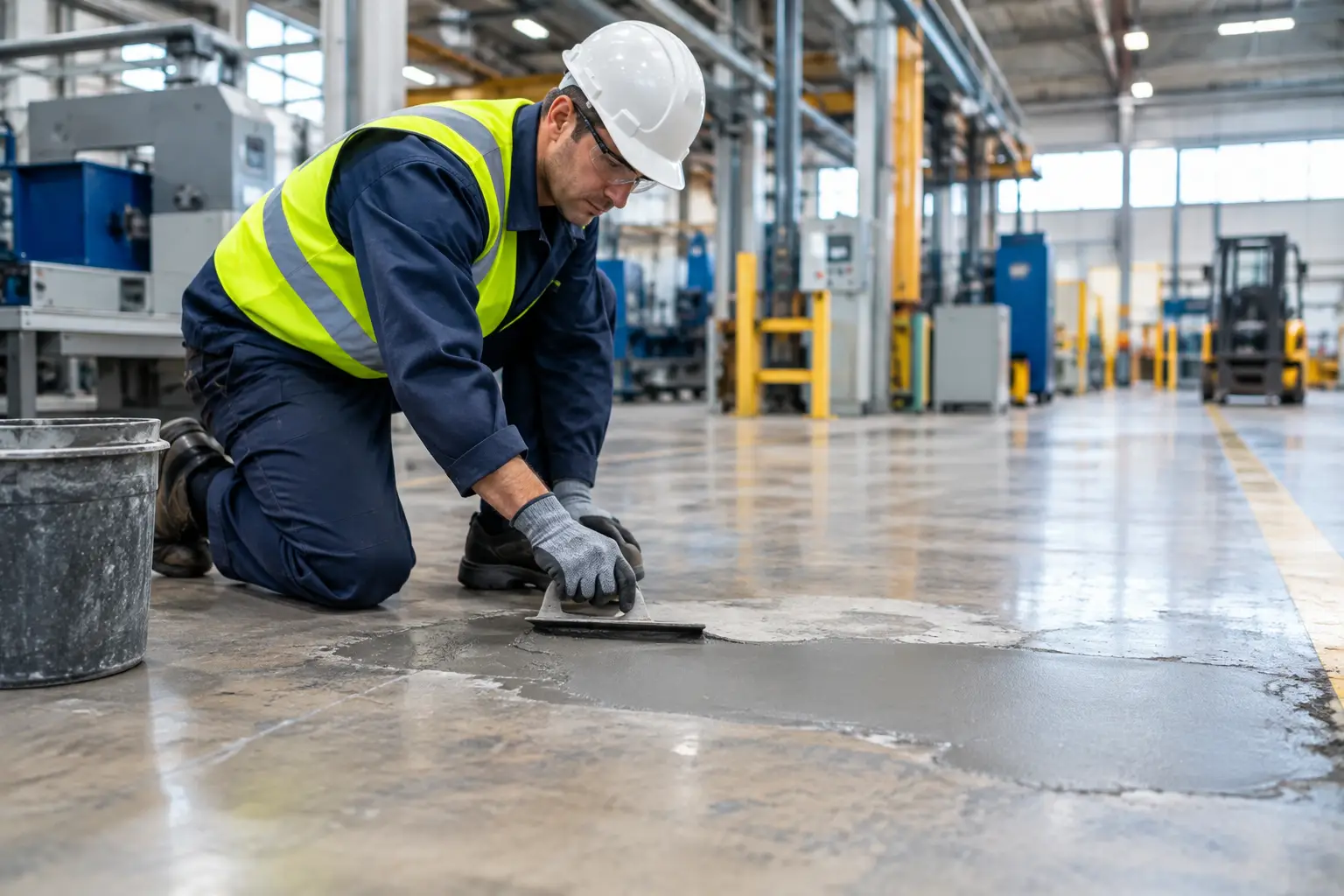
Existing joints deserve the same attention as new construction. Filling an open joint without correcting damaged edges or elevation differences is not a durable repair. The repair must restore support, profile, and bond, then be finished to suit the traffic requirement. For robotics, quality control at the repair edge is as important as the repair material itself.
Surface Performance Must Match the Environment
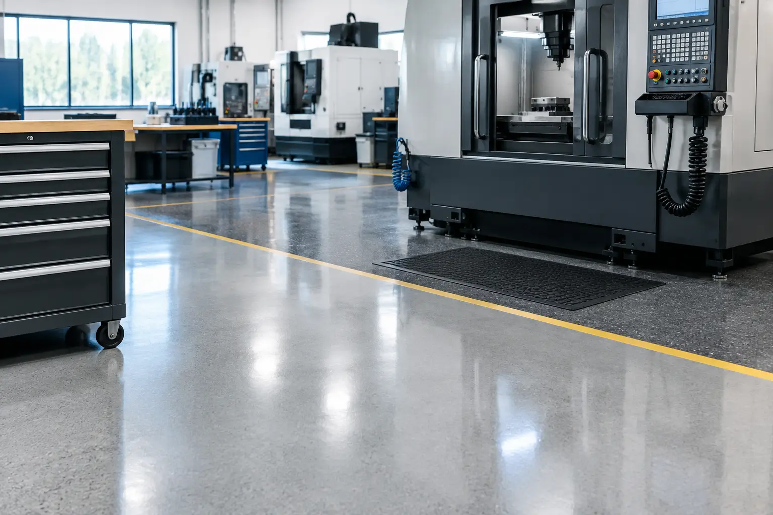
Robots depend on consistent traction and a clean running surface. That does not mean every robotic facility needs a highly polished floor or a thick resin system. It means the surface must perform under the facility's specific conditions.
In dry warehousing, the priority may be abrasion resistance, dust control, joint durability, and a smooth, predictable travel surface. In food, beverage, pharmaceutical, or washdown environments, chemical resistance, sanitation, moisture management, and slip resistance may carry equal weight. A floor that is easy for a robot to travel across may not be appropriate if it becomes unsafe for personnel during wet cleaning.
Coatings and resinous systems should be selected based on exposure, substrate condition, traffic, cleaning practices, and downtime window. They can provide chemical resistance, cleanability, color zoning, and a controlled finish, but they require disciplined surface preparation. A coating applied over weak, contaminated, or moisture-affected concrete will not deliver its intended service life.
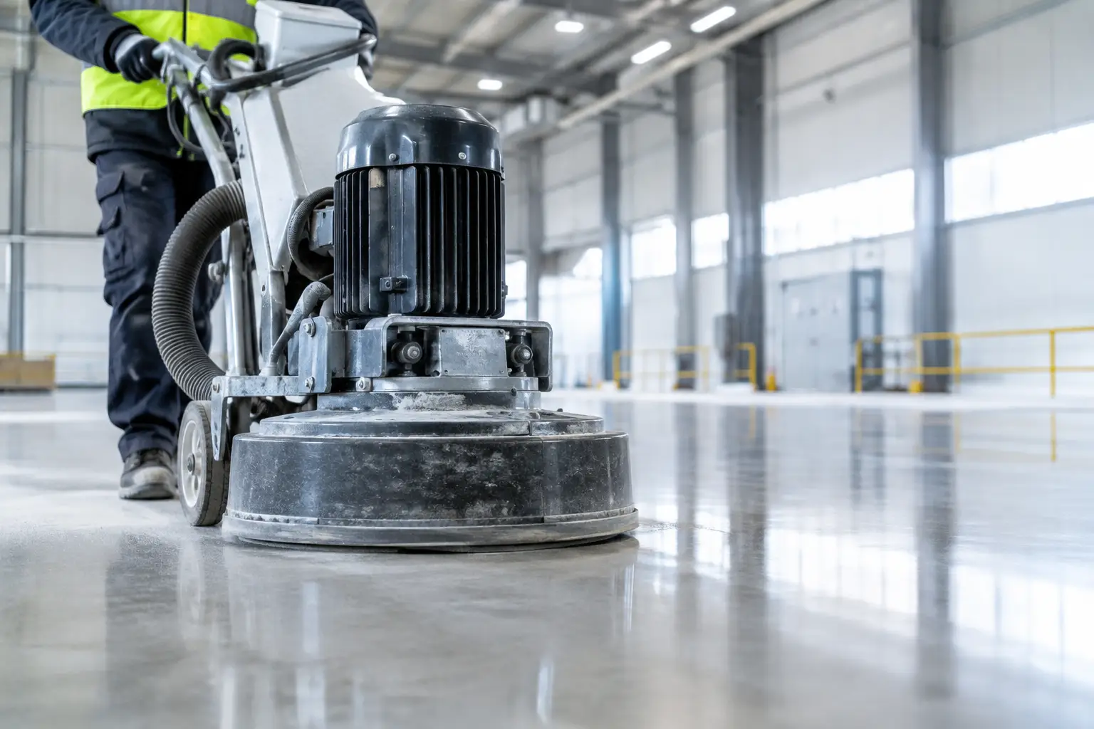
Grinding and floor upgrades are often the practical route for existing buildings. Proper grinding can remove high spots, improve transitions, prepare surfaces for coatings, and correct localized defects. It is not a substitute for evaluating slab movement, structural cracking, or widespread profile deficiencies. The repair scope should address the cause of the problem, not only its visible result.
Guidance Systems Require Installation Precision
Some facilities use wire guidance to establish highly controlled vehicle travel paths. The wire itself is only one part of the system. The routed channel, wire placement, backfill material, finished profile, and verification process all affect performance.
Poorly executed wire guidance installation can create a weak line in the slab surface or leave an uneven patch that becomes a recurring wheel impact point. The channel must be accurately routed, cleaned, filled, and finished flush with the surrounding floor. It must also be protected from traffic and cleaning practices that could damage the installation over time.
Even where robots use laser, camera, QR-code, or natural-feature navigation rather than embedded wire, floor condition still influences guidance reliability. Dust, spalling, reflective glare, standing water, and inconsistent markings can interfere with the broader operating environment. Navigation technology does not eliminate the need for a controlled floor surface.
Specify Verification, Repairs, and Uptime Planning
A strong specification does not end at material selection. It defines how work will be checked, accepted, and maintained. That includes substrate testing where coatings are involved, flatness or profile testing where required, joint inspection, repair acceptance criteria, and documentation of completed work.
For active facilities, sequencing is equally important. Flooring work can affect traffic routes, rack access, sanitation, and production schedules. The contractor should plan containment, cure times, equipment access, shift work, and reopening requirements around the operation. Fast return to service is valuable only when the installed system has reached the strength and cure condition required for robotic traffic.
Facility teams should also establish a repair standard before defects become urgent. Define how cracks, failed joint filler, spalls, and worn travel lanes will be assessed and repaired. This prevents temporary fixes from becoming permanent obstacles in critical robot routes.
Osis Group approaches these projects as operating-floor systems, not commodity concrete or coating work. Superflat floors, jointless systems, floor grinding, wire guidance, and joint repair must be coordinated with the equipment that depends on them.
The best time to protect robotic uptime is before the first vehicle runs. Specify the floor around real operating conditions, verify the finished result, and treat every joint, transition, and repair as part of the route.